OXI EVO Pellet Burner
Table of Contents
- Description and Function
- Requirements to the Fuel
- Scope of Supply
- Design and Operational Features
- Burner Technical Specifications
- Overall and Mounting Dimensions of the EVO Model Range
- The Burner Installation
- Electrical Schematic Diagram
- Manufacturer Settings. Basic parameters
- Start-up and Shutdown
- Main Operating Modes
- Basic Arising Problems
- Requirements for the Safe Operation
- Burner Checkout
- Disposal of the Burner at the End of its Service Life
1. Description and Function
EVO series burners are designed to combust solid fuel in the form of pellet grains with varying degrees of contamination and grain sizes (granulometric composition and other requirements to the fuel are described in Section 2). The burner is operated automatically without the need for constant monitoring and presence of the personnel. Movable grate bars of the OXI burner prevent the slag generated during pellet grains combustion from sticking to the walls of the combustion chamber. The slag is moved forward and out of the combustion chamber by the cyclic forward motion of the grate bar grasses group. Combustion of both highquality fuel and agro pellets is significantly improved due to the ceramic coating of the combustion chamber. Selfsustaining combustion is ensured by a uniform air supply from under the grate bar grasses with preliminary separation into primary and secondary combustion air.
The burner is designed to be operated in central heating boilers on solid fuel, as well as on some gas-fired boilers the design of which supports maintenance of the boiler heat exchanger.
The burner is a device not disruptive to the ecological balance of the planet ecosystem. Environmental neutrality is ensured by the use of fuel from the renewable energy sources. At the same time, the burner operation consumes minimal electrical energy. The burner is regulated by the controller adjusted by the user and responsible for the optimum values of the operating parameters, such as: fuel dosage, control of the combustion air, flame brightness, boiler temperature, etc. The burner controller is specifically designed to control a complex of heating system composed of solid fuel boilers with pellet burners and basic automatic control units (e.g. a room thermostat). The burner controller is additionally equipped with a boiler and DHW temperature sensors. The controller can be connected to the control pumps, as well as to GSM alarm unit.
The controller operation algorithm provides for such emergency situations as overheating, sudden extinguishing of the flame or unplanned depletion of fuel reserves in the burner fuel hopper. Automation system of the burner is resistant to both short-term and long-term sudden power outages. The burner design provides for the possibility of after-combustion of fuel dosage in the de-energized combustion chamber without impacting both the design elements of the burner itself and the boiler equipment.
The dosage and feeding of the pellet grains is provided by a spiral conveyer included in the standard delivery package from a special container, i.e. a pellet hopper, which in its turn can be purchased optionally. The conveyor design provides for installation into an arbitrary hopper with different relative location in the boiler room. Note: this may require certain modifications to the hopper. To this end, the spiral conveyers are optionally available in different lengths.
The burner maximum efficiency is only reached with the proper quality fuel pellet grains. Specifications of such pellets are presented in Section 2.
2. Requirements to the Fuel
This burner efficiency is guaranteed with the following raw wood pellet grains:
|
Parameter
|
Value
|
|
Diameter
|
6 – 8 ± 1, mm
|
|
Length
|
6 – 60, mm
|
|
Packed density
|
650 ± 100 kg/cubic meter.
|
|
Specific calorific efficiency
|
14.5 – 19 MJ/kg
3,460– 4,540 kcal/kg
|
|
Humidity
|
≤ 10%
|
|
Ash content
|
≤ 5%
|
|
Dustiness
|
≤ 3%
|
The burner rated capacity is stated under the condition of operation on the pellet grains manufactured in accordance with ENplus standard. For the pellet grains with different values of caloric content, ash content or moisture content, the burner rated capacity will differ, towards the reduction in the capacity.
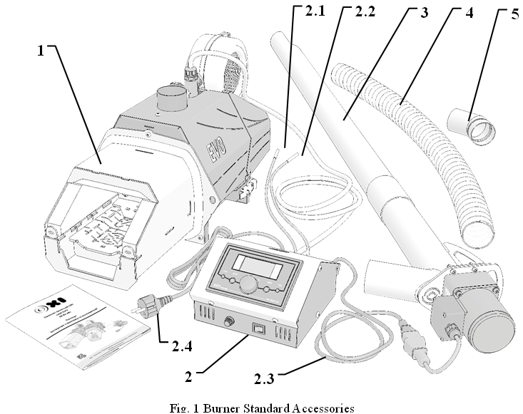
3. Scope of Supply
|
|
Standard Accessory
|
|
No.
|
Component
|
|
1.
|
OXI EVO series Burner
|
|
2.
|
OXI / KEY / Plum controller. Minimum accessory:
|
|
2.1
|
Boiler temperature sensor
|
|
2.2
|
Feeder overheating sensor
|
|
2.3
|
Spiral conveyer connection cord
|
|
2.4
|
Power cord
|
|
3.
|
Fuel feeding spiral conveyer. Standard length is
1.5 m with optional extension of up to 3 m
|
|
4.
|
Flexible hose made of fusible polymer in 1m length. For connection of the burner elbow to the spiral conveyer
|
|
5.
|
Burner elbow. 360° rotatable
|
|
Optional Accessories
|
|
No.
|
Component
|
|
6.
|
Fuel feeding spiral conveyer of the required length and capacity
|
|
7.
|
Pellet hopper is a storage of the required dimensions and capacity
|
|
8.
|
Fusible corrugated hose of the required length.
|
|
9.
|
Automatic electronics (GSM module, etc.)
|
|
10.
|
Boiler doors, both new and modification of the existing ones
|
OXI EVO series burners are supplied as standard, which enables installation of the burner into the boiler, its configuration and maintenance in the standard mode. Additional accessories are optionally available to extend the burner functionality.
|
8
|
Linear grate bar cleaning drive
|
|
9
|
Air distribution control system
|
|
10
|
Electrical switching unit
|
|
11
|
Flame sensor
|
|
12
|
Automation system connection socket
|
|
13
|
Burner casing
|
|
14
|
Stationary grate bar
|
|
15
|
Igniter replacement manhole
|
|
16
|
Flexible screw-shaped scroll
|
|
No.
|
Component
|
|
1
|
Combustion chamber (two options)
|
|
2
|
Grate bar grass
|
|
3
|
Combustion chamber ceramic coating
|
|
4
|
Ceramic fuel igniter
|
|
5
|
Combustion air pressurizer fan
|
|
6
|
Combustion chamber feeder
|
|
7
|
Burner housing
|
4. Design and Operational Features
Fig. 2 OXI EVO Series Pellet Burner Construction Diagram
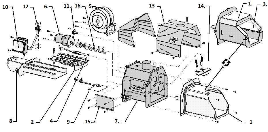
OXI EVO series burner is assembled from individual components into a complete modular multifunctional device.
The burner operation is initiated with the intake of pellet grains from the storage hopper by the screw-shaped scroll. The scroll is driven by the spiral conveyer drive, pulling the pellet grains into the spiral conveyer pipe cavity and then conveying it to the discharge opening. The spiral conveyer drive is regulated by the controller and is capable of operating in various modes, alternating between operation and downtime. This is how a dosage of fuel of a particular mass is formed. Then the pellet grains are freely poured out. The pellet grains passing through the fusible hose and the burner elbow fall by gravity into the feeder 6 cavity, which advances a portion of fuel directly into combustion chamber 1 on grate bar grass 2.
This is followed by activation of ceramic igniter 4 (spark lighter), operated in conjunction with fan 5. In the ignition mode, the fan supplies a limited amount of air, which is quickly heated to the high temperatures by the igniter (the temperature of the spark lighter operating surface is approximately 1,000°C). The heated air affecting the pellet grains causes their spontaneous combustion.
Once the flame of sufficient brightness is detected by photo sensor 11, the automatic equipment switches the burner into the ignition stabilization mode. In this case, the ceramic igniter is disabled and the amount of air and fuel fed to the burner is smoothly increased until the maximum capacity mode is reached.
Combustion chamber 1 is made of heat-resistant AISI 310S steel and is designed for long-term operation at temperatures of up to 1,150˚С. The size dimensions and location of the openings on grate bar 2 ensure stable combustion in the burner, as well as the best combustion efficiency and minimum thermal deformations of the grate bar grass.
The ceramics design of combustion chamber 3 enhances combustion efficiency, resulting in cleaner combustion as compared to the burners designed with cooled metal combustion chamber housing.
However, in the cases when low quality pellets with low ash melting point or agro pellets are used for the burner operation, high temperatures in the burner combustion chamber can cause sintering of some of the
|
Minimum capacity, kW
|
18
|
37
|
67
|
|
Supply voltage, V/Hz
|
230/50
|
|
Average power consumption, W
|
48
|
|
Ignition power consumption, W
|
407
|
|
Total length, mm
|
601
|
636
|
671
|
|
Total height, mm (excluding elbow)
|
341
|
|
Total width, mm
|
273
|
|
Combustion chamber height, mm
|
139
|
160
|
180
|
|
Combustion chamber width, mm
|
142
|
162
|
182
|
|
Combustion efficiency
|
>98%
|
|
Achievable boiler efficiency
|
<92%
|
|
Smooth power modulation
|
Yes
|
|
Complete with fuel spiral conveyer (1.5 m)
|
Yes (Ø70 mm)
|
|
Complete with fusible corrugated hose
|
Yes (1 m)
|
|
Peak under pressure in the boiler, Pa
|
20
|
|
EVO series burner weight, kg
|
18
|
21
|
24
|
|
Fuel spiral conveyer weight, kg (1.5 m)
|
11
|
ash into quite solid particles. Such particles can significantly reduce the burner autonomous operating time without the need for intervention and cleaning. Batch action linear drive 8 is provided, and part of the grate bar grass is manufactured movable in the burner design to eliminate the negative effects caused by the use of low-quality pellet grains. Under the control of the automation, the linear cleaning drive brings the grate bars in operation with a certain regularity, which is best suited to a given quality fuel and ensures the burner maximum possible autonomous operating time, even when operating on agro pellets.
|
Parameter
|
Model
|
|
Ec14
|
Ec16
|
Ec18
|
|
Rated capacity, kW
|
26
|
52
|
82
|
|
Minimum capacity, kW
|
18
|
37
|
67
|
|
Supply voltage, V/Hz
|
230/50
|
|
Average power consumption, W
|
48
|
|
Ignition power consumption, W
|
407
|
|
Total length, mm
|
601
|
636
|
671
|
|
Total height, mm (excluding elbow)
|
341
|
|
Total width, mm
|
312
|
|
Combustion chamber height, mm
|
169
|
190
|
210
|
|
Combustion chamber width, mm
|
201
|
221
|
241
|
|
Combustion efficiency
|
>98%
|
|
Achievable boiler efficiency
|
<92%
|
|
Smooth power modulation
|
Yes
|
|
Complete with fuel spiral conveyer (1.5 m)
|
Yes (Ø70 mm)
|
|
Complete with fusible corrugated hose
|
Yes (1 m)
|
|
Peak under pressure in the boiler, Pa
|
20
|
|
EVO series burner weight, kg
|
22
|
25
|
29
|
|
Fuel spiral conveyer weight, kg (1.5 m)
|
11
|
Burners operation experience suggests that when changing the fuel to low-quality pellets where the burner was operated on high-quality pellets with high efficiency for a long time, high-quality combustion on the burners of classic design is not always possible to be achieved. For this reason, air distribution controller 9 has been integrated into the design of the OXI EVO series burner, which provides a wide range of air dosages supplied to different combustion zones. Thus, the maximum efficiency of combustion of different fuels with significantly different properties can be achieved in a single burner.
Burner housing 7 also incorporates electrical switching unit 10. Housing cover 13 encloses the burner housing protecting it from damage and external impact on the burner components.
The spiral conveyer provides a measured fuel feed to the burner. The spiral conveyer is operated by the controller. The spiral conveyer is connected to the burner with a low-melting corrugated hose protecting the pellet storage area from the effects of the inverted flame.
The burner is designed with the following successive fire safety levels in emergency modes:
- Movable grate bars prevent accumulation of the unburned pellet grains in the combustion chamber.
- The feeder forms a gap in the fuel jet and ensures a rhythmic feeding of the fuel dosage into the combustion zone.
- Stocker volume pressurization prevents the flame jet from expanding into the fuel line.
- An overheat sensor is provided on the burner elbow to alert of a potential fire.
- As the last of protection level, the fusible corrugated hose melts and prevents flames from spreading towards the fuel storage area.
5. Burner Technical Specifications
|
Parameter
|
Model
|
|
E14
|
E16
|
E18
|
|
Rated capacity, kW
|
26
|
52
|
82
|
The burner rated capacity is stated under the condition of operation on the pellet grains manufactured in accordance with ENplus standard. For the pellet grains with different values of caloric content, ash content or moisture content, the burner rated capacity will differ, towards the reduction in the capacity.
|
Part Number
|
sX, mm
|
sD,
mm
|
sd,
mm
|
sK, mm
|
sL, mm
|
Burner capacity, kW
|
|
ШК3GN100K-70-601500
|
1,430
|
70
|
60
|
150
|
1,61 5
|
18-52
|
|
ШК4GN50K-70-601500
|
1,430
|
70
|
60
|
150
|
1,63 0
|
67-82
|
|
|
|
|
|
|
|
|
|
|
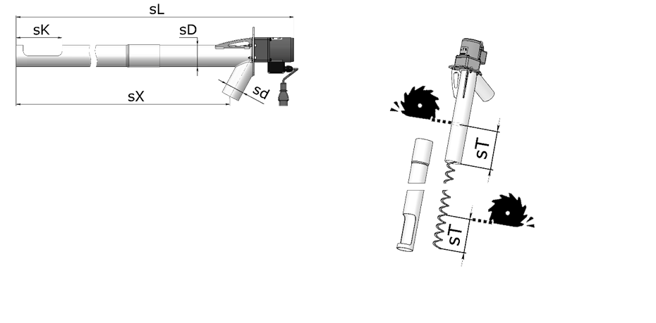 The burner is supplied as standard complete with a 1.5 m long fuel spiral conveyer. Fuel spiral conveyers of different lengths are optionally available. At that, the design of any spiral conveyer enables reduction of its length in site
Fig. 3 Fuel Spiral Conveyer Standard Sizes
during the burner installation, which provides for the boiler room ergonomics.
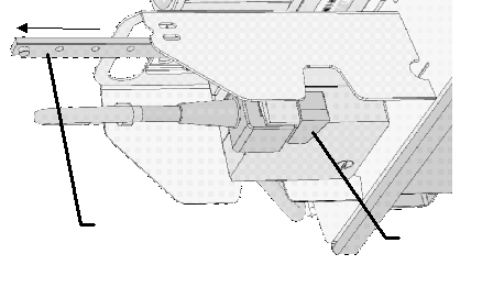
To reduce the length of the fuel spiral conveyer, its final length must be calculated.
For example, if for the proper installation of the burner a 1.2 m long spiral conveyer (size sX) is required up to the discharge opening, it means that the Fig. 4 Reduction of the Fuel Spiral
standard spiral conveyer is not acceptable. Conveyer Length
This means that the spiral conveyer must be shortened by 230 mm. To do so, tighten the main spiral conveyer pipe with the feed block opening following the instructions in Fig. 4. The spiral conveyer is telescopic jointed. Then, using the cut-off wheel of the angle grinder, remove part of the scroll and the upper pipe of the spiral conveyer with a length of sT.
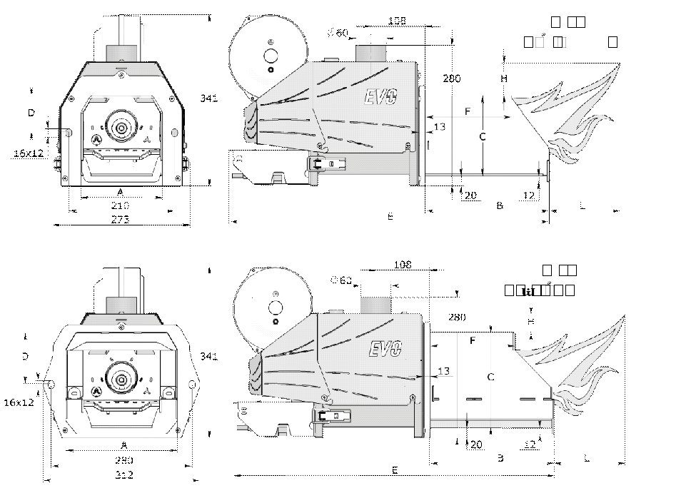
6. Overall and Mounting Dimensions of the EVO Model Range
|
Model
|
Capacity, kW
|
A
|
B
|
C
|
D
|
E
|
F
|
H
|
L
|
|
EA140
|
18
|
142
|
213
|
139
|
52
|
601
|
133
|
100
|
200
|
|
EB140
|
26
|
142
|
213
|
139
|
52
|
601
|
167
|
130
|
260
|
|
EA160
|
37
|
162
|
246
|
160
|
72
|
636
|
171
|
160
|
320
|
|
EB160
|
52
|
162
|
246
|
160
|
72
|
636
|
260
|
190
|
380
|
|
EA180
|
67
|
182
|
281
|
180
|
92
|
671
|
212
|
220
|
440
|
|
EB180
|
82
|
182
|
281
|
180
|
92
|
671
|
247
|
250
|
500
|
|
EAC140
|
18
|
201
|
211
|
169
|
82
|
601
|
127
|
100
|
200
|
|
EBC140
|
26
|
201
|
211
|
169
|
82
|
601
|
162
|
130
|
260
|
|
EAC160
|
37
|
221
|
246
|
190
|
102
|
636
|
169
|
160
|
320
|
|
EBC160
|
52
|
221
|
246
|
190
|
102
|
636
|
204
|
190
|
380
|
|
EAC180
|
67
|
241
|
281
|
210
|
122
|
671
|
209
|
220
|
440
|
|
EBC180
|
82
|
241
|
281
|
210
|
122
|
671
|
244
|
250
|
500
|
when used as intended. As a rule, EVO series burner is installed in an
7. The Burner Installation
assembled boiler room on the boilers operating on solid
The best result in the burner operation is achieved fuel with performance specifications corresponding to the
parameters of the burner.
Depending on the boiler design, several options are provided for installing the burner in the boiler combustion chamber. Cutting in to the lower boiler door is the most popular installation method.
The burner must be located so that the burner maintenance is not complicated and its main components are accessible. Easy cleaning and direct control of the combustion chamber must be ensured.
In case the burner is installed in the boiler door that opens, the burner structural components must not reach the boiler surfaces (the burner must not cling to the boiler when the door opens). If the door width is too narrow, asymmetrical installation of the burner combustion chamber in the door, closer to the door rotation hinges, is acceptable. If the burner still abuts against the side frame of the door opening even with the specified arrangement, a remote-mount flange must be used to extend the burner outward from the boiler combustion chamber. For the latter case, making a new boiler door specifically to install the burner, while retaining the old one, would be recommended: this will enable quick enough switching to wood heating at any time. Please consult the manufacturer technician to determine the best solution for installing the burner in a particular boiler.
A pellet hopper of a certain capacity must be provided in the boiler room to enable the burner to operate for a significant period of time, during which it can be kept unattended. The hopper must be suitable for a fuel spiral conveyer with a diameter of 70 mm. Such a hopper in an assortment of varieties can be purchased from the burner manufacturer, or an existing hopper made of noncombustible materials can be used.
Particular attention must be paid to the spiral conveyer intake opening at the bottom. While in operation, the feeding screw must be completely covered with pellet and protected from contact with the personnel. A rotating screw can cause serious injury.
The burner must only be installed by specialized certified personnel and in compliance with the instructions specified in this Service Manual.
Standard Installation Procedure:
- Measure the boiler doors and determine the optimum burner attachment point and the need for a remote-mount flange. The burner must be installed in the boiler in accordance with the dimensions and location described in the installation lay-out (Fig. 5).
- In case the delivery package is not provided with an additional boiler door for the burner, provide a hole for the burner combustion chamber and fixing holes to fix the burner to the boiler door (refer to Section 6). If the door requires installation of a remote-mount flange, it must be installed by a qualified technician and in accordance with the instructions specified in this Manual.
A smoke pump must be installed for the boiler lacking sufficient vacuum (less than 20 Pa).
- Remove the burner elbow. Then install the burner in the door opening attached to the boiler and secure it by tightening the screws. Make sure the burner door opens and closes freely. The burner combustion chamber and the boiler ash pan must be freely accessible.
- Install the automation unit either on vertical or horizontal panel, depending on the selected electrical connection option, so that it is easy to monitor the information display and manipulate the control unit actuators.
- Insert the length-adjusted fuel spiral conveyer (refer to Section 5) into the empty pellet hopper. When the hopper is already loaded with pellet grains, the spiral conveyer can be inserted into the hopper mounting bore using sufficient force along the mounting axis while rotating the spiral conveyer in its helix direction, as if "screwing" it into the pellet. The intake opening must be completely covered with pellets, and no gaps, through which the pellet grains could drop out during the spiral conveyer operation, must remain between the spiral conveyer pipe and the hopper mounting bore.
- Install the burner elbow in the corresponding nozzle of the burner feeder. Adjust the length of the fusible corrugated hose connecting the fuel spiral conveyer and the burner elbow so that it does not interfere with the free opening of the boiler door with the burner installed. With that, the hose axis and the horizon must form an angle of more than 35 degrees for the free flow of pellet grains without formation of clogs, which will cause an emergency shutdown.
- Plug all electrical connections according to the selected wiring diagram. In the most basic version, the head multi-core cord of the controller must be connected to the plug on the burner housing or, if not provided, to the connector of the burner switching unit; the overheating sensor must be installed in the feeder sleeve through manhole 15 Fig. 2. The boiler sensor must be installed in the boiler temperature protection sleeve or, if not provided, securely attached to the boiler feed pipe; the fuel spiral conveyer connection cord must be securely installed in the automation unit connector; all connections must be checked for reliability; wires are ergonomically routed around the furnace room; grounding connection must be checked; igniter connection and correct seating must be checked.
Close the plastic cover of the switching unit in case
it was opened during the installation.
- Connect the controller power cord to a grounded outlet and turn the controller switch on. A message with the controller firmware version will be displayed.
- Run a service “check of the outputs” of the controller by visual inspection of the burner assemblies in accordance with the automatic system Manual.
- Fill the pellet grains into the fuel hopper so that they cover the intake opening of the spiral conveyer if no pellet is available in the hopper. Press and hold the controller “START” button for 5 seconds; the “spiral conveyer filling” mode will be activated.
Simultaneously, the scroll of the fuel spiral conveyer will start rotation involving pellet grains into the intake opening. If the corrugated hose is connected to the burner elbow, disconnect them by lowering the end of the hose into a dry container with a capacity of 5 to 10 liters. In 3-10 minutes after activation of the spiral conveyer, the pipe will be filled with pellet grains, and they will start falling out of the discharge opening into the container. Wait about 1 minute to ensure that the spiral conveyer is filled. Press the controller “STOP” button, pellet grains feeding will stop.
- Batch weight the fuel. To do so, a small container of about 5 liters or a sturdy bag of 10 liters and a timing device are needed.
Calculate the hourly capacity of the spiral conveyer in kilograms (kg/h) using the check weighing method. To do this, switch to the “spiral conveyer filling” mode having previously directed the spiral conveyer hose into the prepared empty container, as well as mark the time with the timing device.
For example, 826 grams of pellet grains were filled into the container after 2 minutes. Taking into account the caloric content of the pellet grains specified in the delivery certificate (for example, 4,100 kcal/kg) calculate the hourly capacity of the spiral conveyer into kilowatts (kW) using the following formula:
kg/hour (spiral conveyer) * kcal (pellet grains) *
0.001163 = kW
In this case, 0.826 kg in 2 minutes = 24.78(kg/h), then: 24.78(kg/h)*4,100(kcal/kg)*0.001163 = = 118.2 (kW).
This means that with the continuous operation of the spiral conveyer, it will ensure operation of 118 kW burner.
Take the hourly capacity of the spiral conveyer for 100% and calculate the fuel weight for maximum and minimum burner capacity as a percentage. To put it simply, calculate how many percent of the time a spiral conveyer should rotate in order to fill the pellet for a certain capacity.
Assuming the installed burner is 37 kW, for which
the minimum capacity amounts to 12 kW (Table of Section 5), then in this example: (37 kW/118 kw=0.31) “Fuel Dose for Max Capacity” = 31%; (12 kW / 118 kW=0.1) “Fuel Dose for Min Capacity” = 10%
- Connect the corrugated hose to the burner elbow. After additional service configuration, the burner is ready to be started.
Attention! The burner combustion chamber must be installed with the grate bar grass in a horizontal position. The burner/boiler connection must be tight to avoid any leakage of the smoke fumes. The use of a gas analyzer is recommended for configuring the burner.
8. Electrical Schematic Diagram
Technical Data of the Automation Controller
|
Parameter
|
Value
|
|
Power supply
|
230 V ± 10%, 50
Hz
|
|
Power consumption (excluding fan and pump)
|
<2 VA
|
|
Temperature measuring range (KTY 81-210)
|
- 9 ÷ 109°C ± 1°C
|
|
Burner temperature measuring
|
- 9 ÷ 109°C ± 1°C
|
|
range (KTY 81-210)
|
|
|
Burner temperature measuring range (RT-1000)
|
- 30 ÷ 500°C ± 3°C
|
|
Boiler temperature control range
|
30 ÷ 90°C ± 1°C
|
|
Software protection of the boiler overheating
|
90 ÷ 99°C ± 1°C
|
|
Hardware protection of the boiler overheating
|
>95°C ± 1°C
|
|
Aggregate output load
|
max. 2 A / 230 V
|
|
x General
|
|
Parameter No.
|
Value
|
|
2.1 Language
|
Russian
|
|
2.7 Outputs testing
|
*1
|
|
3. x Fan 1 operation parameters
|
|
|
3.1 Speed modulation at ignition
|
NO
|
|
3.5 Fan speed at ignition
|
6%
|
|
3.6 Speed at max capacity
|
20%
|
|
3.7 Speed at min capacity
|
7%
|
|
3.8 Attenuation speed
|
100%
|
|
3.10 Fan blowing.
|
YES
|
|
3.11 Blowing time
|
s
|
|
3.12 Blowing interruption time
|
min
|
|
3.13 Blowing speed
|
100%
|
|
4.x Fuel hopper parameters
|
|
|
4.1 Hopper filling time
|
min *2
|
|
4.2 Starting fuel dosage
|
s
|
|
4.3 Fuel feeding cycle
|
s *3
|
|
4.4 Fuel dosage for ignition
|
0% *4
|
|
4.5 Fuel dosage for max. capacity
|
X%*5
|
|
4.6 Fuel dosage for min. capacity
|
Y%*5
|
|
4.7 Stoker operation mode
|
AUTO
|
|
4.10 Stoker extra operation time
|
*6
|
|
4.11 Stoker cleaning time
|
s
|
|
4.12 Hopper ignition
|
YES
|
|
4.13 Hopper ignition temperature
|
80o
|
|
5. x Spark lighter operation par
|
ameters
|
|
5.5 Flame loss delay.
|
s
|
|
5.6 Fuel ignition time.
|
min*7
|
|
5.7 Number of ignitions
|
*8
|
|
5.10 Ignition stabilization
|
YES
|
|
5.11 Ignition stabilization time
|
min
|
|
5.13 Combustion chamber attenuation time
|
min
|
|
x Cleaning mechanism
|
|
|
6.1 Combustion chamber cleaning
|
C
|
|
6.2 Cleaning mechanism operating time.
|
s
|
|
6.3 Cleaning mechanism release time.
|
s
|
|
6.4 Cleaning mechanism downtime.
|
s *9
|
|
x Boiler operation parameters
|
|
9.1 Minimum boiler temperature.
|
30o *10
|
|
9.2 Maximum boiler temperature.
|
90o *10
|
|
9.6 Boiler overheat temperature.
|
o *10
|
9. Manufacturer Settings. Basic parameters
Automation settings specified in the Table are well suited for the burner initial start-up, and are averaged for most OXI EVO series burners. However, these parameter values cannot be considered optimal. Please note that the final settings for this particular burner will not correspond to the specified ones, and their values will be clarified in the process of the burner setup by a technician.
Only the basic parameters of the controller, without which settings the start-up is not possible, are presented in the Table. For a complete list of parameters, refer to RK-2006SPG2 Controller
Manual. The titles of some items may differ due to the differences in menu translation in different versions of the controller firmware.
Notes
|
*1
|
The menu is used during the burner installation or maintenance; see Section 7 “Burner Installation” Clause No. 9.
|
|
*2
|
The parameter is used during the burner installation or maintenance when the “spiral conveyer filling” mode is activated; see Section 7 “Burner Installation” Clause No. 10-11.
|
|
*3
|
Burners operating experience suggests the parameter value of 30 seconds or more for high quality pellets. It can be useful to reduce the cycle time value to 15 seconds for agro pellets. The final decision will be made during the burner configuration.
|
|
*4
|
Burner operating experience suggests that feeding pellet grains is not always advantageous during the ignition. The new batch often shifts the location of the ignitable pellet grains thereby deteriorating the ignition and extending its time. 0% – no fuel is fed during the ignition.
|
|
*5
|
The parameters percentage values are determined by the spiral conveyer batch weight, its hourly capacity. See Section 7 “Burner Installation” Clause No. 11. In case of change of the spiral conveyer position or fuel grade, the hourly capacity of the spiral conveyer must be recalculated. After that, the parameter values must be updated.
|
|
*6
|
This is an extra time to ensure that the pellet grains, which are lagging behind falling through the corrugated hose after the cyclic shutdown of the fuel spiral conveyer, are fed into the combustion chamber from the feeder. 5-10 seconds is an acceptable value, but note that this time in seconds must not be longer than the fuel spiral conveyer downtime, since the feeder will then run continuously. In this case, overheating of the latter is probable.
The acceptable value can be calculated using the following formula:
|
|
|
(4.3 Fuel feeding cycle, sec) * (100%-(4.5 Fuel dosage for max. capacity, %)) /100%
Assume,
“4.3 Fuel feeding cycle” = 30 sec
“4.5 Fuel dosage for max. capacity” = 34% Then:
30 (sec)*(100%-34%)/100 = 19.8 (sec).
It would be reasonable to choose:
“4.10 Stoker extra operation time” = 10 sec, leaving 9.8 seconds of the feeder downtime for cooling.
|
|
*7
|
Operating experience suggests:
Ignition < 2 min – excellent.
Ignition < 5 min – good.
Ignition < 7 min – acceptable.
Ignition < 15 min – requires setting of “3.5 Fan speed at ignition” parameter, as well as testing the spark lighter setting and fuel quality
|
|
*8
|
Operating experience suggests that if the burner is not ignited in 2 ignitions, the causes of unstable ignition must be identified and measures to improve the ignition must be taken.
|
|
*9
|
The cleaning mechanism operation frequency must be selected experimentally for the specific fuel. Operating experience suggests that “6.4 Cleaning mechanism downtime” = 120 sec is appropriate for operating the burner with medium quality fuel (that is, wood pellet with ash content of 2-7%). For agro pellets, the downtime must be reduced up to 1 sec (these include dusty sunflower pellet grains with ash content of 25%). In the case of high-quality ENplus pellets the cleaning can be completely disabled: “6.1 Combustion chamber cleaning” = NO
|
|
*10
|
The coolant control temperatures in the heating circuit are set depending on the heating system type. The specified parameters are appropriate for the initial start-up and brief operation of the burner.
|
- The burner must only be installed and configured by specialized certified personnel and in compliance with the instructions specified in this Service Manual.
- Do not permit inexperienced persons or children to open the burner.
- Read RK-2006SPG2 Controller User Manual before the burner initial start-up.
10. Start-up and Shutdown
- Make sure pellet grains are available in the hopper. Start the water pump if available.
- Activate the burner automation system. The burner will switch to the standby mode.
- In the standby mode, change of the burner basic settings, as well as control of the burner main components availability in the diagnostics menu, are enabled. (Section 7 Clause 9 and Section 9 Clause 2.7 Outputs testing).
- Before the burner initial start-up, as well as after each preventive cleaning of the spiral conveyer, the spiral conveyer pipe must be filled with pellets. Refer to description in Section 7, Clauses 10-11.
- Check the following user menu parameters when starting the burner for the first time:
|
Parameter
|
Value
|
|
1
|
PELLETS
|
|
2
|
60o-90o
|
|
3
|
~5-20
|
- To start the burner, select the “START” command by pressing the “START” button. A brief sound from the fan blowing should be heard. After that, the pellets will be unloaded into the intake combustion throat of the burner elbow through the corrugated hose with subsequent feeding of the pellets into the burner combustion chamber. The igniter and the pressurizer fan will be activated in a short time.
- Once the start-up is successful, the automatics system will indicate the appearance of the flame with a corresponding increase in brightness in the burner combustion chamber. The main parameters of the burner operation are also displayed on the screen.
- FUEL TYPE → WOOD/PELL.
- SET TEMPERATURE
- OFF IGNITION AT BRIGHTNESS
- CURRENT FLAME BRIGHTNESS
- The burner shutdown occurs in the following cases:
- the ”STOP” button is pressed on the control panel; - unsuccessful series of ignition attempts, if the specified flame brightness was not set;
- the set temperature of the burner elbow is exceeded (see Section 9 Clause 4. 13 “Hopper ignition temperature”);
- Upon receiving the shutdown command, the automation system will proceed to the following program:
- the spiral conveyer drive is disabled and the pellets feeding into the burner is stopped;
- the burner is switched to the combustion chamber blowing mode for the preset period of time (see Section 9 Clause 5.13 “Combustion chamber attenuation time”), after which it is switched to the standby mode.
11. Main Operating Modes
The burner operation with different types and grades of fuel may require changes in the controller settings. For this purpose, 4 different settings profiles for different fuels can be set in the controller. The settings profiles are saved in the user menu under the name “Fuel Type 1-4”. When changing the pellets, the appropriate settings profile must be selected in the “Fuel Type” menu section.
Once all the instructions in Section 10 have been completed, the burner can be operated in a continuous mode. Uninterrupted operation is achieved with availability of fuel in the pellet hopper and proper operation of the heating system. When the pellet burner is operated by the KEY controller, the following operating and emergency statuses of the burner are probable:
|
MAX. CAPACITY
|
Constant fuel and air supply with controlled temperature rise dynamics at the constant burner capacity.
|
|
Preventive smooth reduction of fuel and air supply, and hence the burner capacity in order to raCAPACITY MODULATIONise the boiler temperature to the set value without its exceeding, and maintaining of the heating system in a given temperature range.
The modulation primary objective is to reduce the number of ignitions and attenuations by varying the burner capacity.
|
|
MINIMUM CAPACITY
|
Constant fuel and air supply to maintain combustion without increasing the temperature.
|
|
BLOWING
|
Removal of clogging by shortterm increase of the fan capacity up to 100% (see Section 9
Clauses 3.10-3.11)
|
|
AFTER COMBUSTION
|
Before switching to the ATTENUATION mode, the residual fuel is slowly after combusted until its all-burnt condition.
|
|
ATTENUATION
|
The constant blowing down mode is activated to cool the burner structure in the absence of flame (see Section 9 Clause 5.13).
|
|
FILLING
|
The spiral conveyer filling mode. The burner is disabled at this moment (see Section 9
Clause 4.1).
|
|
ALARM SIGNALS
|
Information about the problem is displayed on the screen. Additionally, depending on the fault type, the internal buzzer may also be activated. See Section 12 for more information.
|
|
Status
|
Description
|
|
STOP
|
The boiler control is disabled. Pumps operation control is enabled, but temperature-
controlled automatic ignition is not activated.
|
|
STANDBY
|
Pumps operation control is enabled. Upon reaching the min temperature, automatic ignition is activated.
|
|
IGNITION
|
The burner automatic ignition.
|
|
IGNITION STABILIZATION
|
Smooth increase of fuel and air supply until MAXIMUM
CAPACITY mode is reached.
|
12. Basic Arising Problems
Problems Caused by Installation Errors:
|
No.
|
Problem
|
|
A.
|
Automation system can be damaged by flames and smoke when the boiler door is opened. The automation system location is inconvenient for monitoring and control.
|
|
B.
|
The automation system is conveniently installed for monitoring, but will be damaged during the pellet grains loading from the bag into the hopper.
|
|
C.
|
The automation system is installed inconveniently for monitoring and may be damaged by the hopper cover.
|
|
D.
|
Poor sealing between the burner and the door.
Gases penetrate into the combustion chamber.
|
|
E.
|
The spiral conveyer is installed not deep and tightly enough in the hopper, the pellet grains spill.
|
|
F.
|
Improperly selected relative location of the hopper and the door opening angle. The corrugated hose is stretched.
|
|
G.
|
Insufficient inclination angle of the corrugated hose. It is clogged with dust and pellet grains.
|
|
No.
|
Failure
|
Reason
|
Solution
|
|
1.
|
The burner is not ignited.
Alarm signal: “No fuel”
5
|
• Pellet hopper ran out of pellet grains.
|
• Fill the hopper with pellets.
• Restart the automation system.
• Fill the spiral conveyer.
|
|
• The fuel spiral conveyer is jammed.
• Failure of the spiral conveyer drive.
|
• Release the spiral conveyer.
• Clean it if necessary.
• Run an outlet test for the spiral conveyer.
• Replace the spiral conveyer if necessary.
• Fill the spiral conveyer.
|
|
• The spark lighter is either burned out or no electrical contact.
|
• Run an outlets test for the spark lighter.
• Visually check the heating element glow.
• Replace the spark lighter if necessary.
• Make sure it is correctly installed in the sleeve and free of clogging.
|
|
• Failure of the feeder drive.
(the corrugated hose is completely filled with pellet grains)
|
• Run an outlets test for the feeder.
• Replace the feeder if necessary.
|
|
• Combustion chamber slagging.
• The boiler ash pan is filled to the level of the burner combustion chamber.
|
• Clean the combustion chamber.
• Clean the boiler ash pan.
|
|
• The photo sensor photosensitive element is damaged or dirty.
|
• Check the increase of the CURRENT FLAME BRIGHTNESS by lighting a
flashlight into the combustion chamber.
• Clean the photosensitive element or replace the photo sensor if necessary.
|
|
2.
|
Message: "Hopper
Ignition"
6
|
• The burner housing is too hot due to improper operation.
|
• Eliminate any defects causing the housing to be heated.
|
|
• The back draft dampener is not completely closed causing hot gases draft into the fuel pipe.
|
• Fix the breakage of the back draft dampener or clean it.
|
|
• Considerable decrease in the boiler discharge, the boiler is probably dirty.
|
• Check the draft, clean the boiler.
|
|
• Due to the seasonal changes in the Sun trajectory, its light heats the burner housing through the furnace room window.
|
• Use non-flammable curtains on the window.
|
|
• The boiler ash pan is filled to the level of the burner combustion chamber.
|
• Clean the boiler ash pan.
|
|
3.
|
Message:
"Boiler Overheating"
7
|
• Maximum boiler temperature is exceeded
|
• Wait for the temperature to decrease.
• Use capacity modulation.
|
|
• The boiler preset temperature is too low.
|
• Change the preset temperature settings.
|
|
• The forced circulation of the coolant through the boiler has
|
• Turn on the pump, it may have failed.
• Be sure to troubleshoot the overheating
|
5. Alarm: No fuel
6. Alarm: Hopper Ignition
7. Alarm: Boiler Overheating
|
|
|
stopped.
|
reason.
|
|
4.
|
The AFTER
COMBUSTION mode is
not changed into
ATTENUATION mode.
|
• The photo sensor contact is damaged.
|
• Replace the photo sensor.
|
|
5.
|
The burner excessively smokes.
|
• Not enough air for combustion.
|
• Add combustion air, configure the burner.
|
|
• The fan is damaged.
|
• Run the fan output test, inspection.
Replacement.
|
|
• The fan inlet is blocked.
|
• Release the inlet from the blockage.
|
|
6.
|
Excessive ash. Unburned pellets are observed.
|
• Poor quality pellet.
• The cleaning mechanism is damaged, or the movable grate bar is jammed.
• The cleaning drive is unlocked with a magnetic key fob, see Fig. 10.
|
• Change the pellet supplier.
• Run an output test for the cleaning mechanism. Clean and inspect.
• Remove the magnetic key fob.
|
Any manipulations with the burner components, fuel spiral conveyer or automation system must be performed with the de-energized and cooled down burner. Non-compliance with safety precautions can result in serious
injury.
13. Requirements for the Safe Operation
The pellet burner is a high power heat device; to ensure safe operation of the burner the basic rules of its operation must be observed.
- Do not open the boiler door with the burner installed during the operation of the burner.
- In case of pellet grains or dust ignition on the burner surface, immediately disconnect it from the power supply network before extinguishing the fire with appropriate means.
- The boiler room must be kept clean, ensure no flammable materials are stored in the furnace room. 4. The burner must be operated by the qualified personnel who have been instructed and have read the User Manual.
- The boiler, heaters and DHW components must be kept in proper operating condition.
- Note particularly the moisture sources located near the burner. Contact of the burner construction components with water considerably increases the risk of electric shock.
- The burner feeder and the fuel spiral conveyer are equipped with rotating components and drives of significant power. Keep your fingers and other objects out of the rotation area to the maximum extent possible.
- Modification of the burner design or installation of any electrical consumers not provided by the Manufacturer and their connection to the burner electrical diagram is strongly prohibited.
- The burner is a high heat emitting device; some burner components operate at a high temperature. For example, the combustion chamber ceramic coating can be heated up to 1,200°C. Be careful when handling the burner.
- No operation of the burner is permitted unless the installation has been approved by an authorized service technician.
- Installation and operation of the burner in the boilers that are not appropriate is prohibited.
- The burner cannot function as an open flame source.
- Do not leave any objects on the burner surfaces.
- Do not use other ignition methods, in particular, flammable liquids.
- The burner must be operated with the cover installed. All sensors must be installed in their original positions at all times while the burner is in operation.
Please note that only reasonable use of the equipment can be safe. All potential emergency situations cannot be anticipated.
14. Maintenance. Burner Checkout
The burner must be cooled down before any maintenance operations. The burner must be disconnected from the power supply network.
General Recommendations
To ensure the burner uninterrupted operation and to maximize the burner service life, the following guidelines must be observed:
- Clean the combustion chamber regularly. The frequency of cleaning depends on the fuel quality, its ash content and humidity, as well as on the operating mode of the movable grate bar. On average, such cleaning is required once a week.
- Use high-quality certified fuel.
- Do not allow fuel containing impurities to be combusted in the burner. Use only wood and agro pellets. Beware of woodworking pellet grains, particleboard contains poisonous toxic substances.
- The boiler room must provide sufficient air supply and ventilation.
Air Distribution Control.
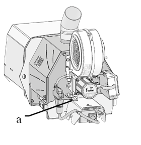 Greater combustion process efficiency can be achieved by proper distribution of secondary and primary combustion air of the burner. OXI EVO series pellet burner is equipped with an independent pressure reduction system, which enables fine control of the air supply and distribution in the burner combustion chamber. The distribution valve control lever is located next to the grate bars drive
connector (Fig. 7, a)
If more air is required under the
movable grate bar grass, the lever Fig. Fig.7 Air Control Lever
8 is shifted along the bar to position 1. If
more air is required for complete combustion of the volatiles, then more air is supplied through the front wall, and the levers are shifted to position 2.
Fix the lever in the desired position by turning, Fig. 8.
Replacing the Spark Lighter
The igniting unit may be replaced by a service representative of the manufacturer, or by a qualified person instructed and authorized to work with voltages of up to 1 kW.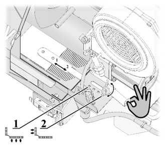
- De-energize the cooled burner.
- Remove the cover of the switching unit A 9 and disconnect the spark lighter terminal (FIRE).
- Remove the screws b 9.
- Remove the spark lighter cover c in such a way as to fully open the opening. Loosen the spark lighter locking screw v.
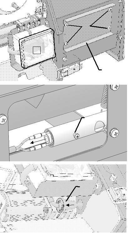 Fig. 8 Air Distribution Valve Lever.
- Pull the spark lighter by the wire along its axis without much effort until the sealed lead-in G is out of its mounting bore.
- Install the spark lighter in the reverse order. The spark lighter must fit tightly in the burner mounting sleeve and reach the end.
Fig. 9 Replacing the Spark Lighter
Cleaning the Under-Grate Bars Area.
To dismantle the grate bars, de-energize the cooled burner.
Remove the ash from the grate bars surface with a special brush into a pre-prepared non-flammable container or into the boiler ash pan.
Shift the cleaning rod to the rear position. To do so, press and hold the locking button M Fig. 10, now the drive can be freely manually moved. Pull the drive rail K, bringing it to the extreme rear position. 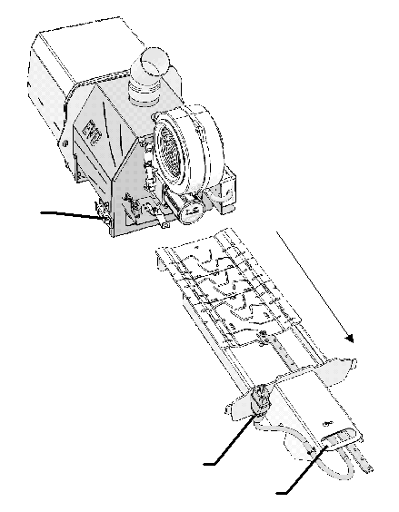
Then, disconnect the grate bars drive connector T and unfasten the safety locks F on the both sides Fig. 11. Now pull the grate bars assembly by the handle P until the grate assembly is completely out of the burner.
Clean the burner combustion chamber by removing all ash and slag. Install the grate bars assembly in the reverse
Fig. 10 Unlocking the Cleaning Drive
Fig. 11 Dismantling of the Grate Bars order.
15. Disposal of the Burner at the End of its Service Life
Burners that have become unserviceable due to improper operation, accidents or due to expiry of their service life must be subject to disposal. The burners contain no materials or components hazardous to the environment and are subject to disposal in accordance with the general procedures adopted by the Company or in accordance with General Environmental Regulations.
tPell
Pellet burner controller

Using the device
General view
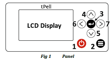
Buttons:
1.  Power On / Off
2.  Back
Back
3. ↵ Enter
4. ∧ Up
5. ∨ Down
6. < Left
7. > Right
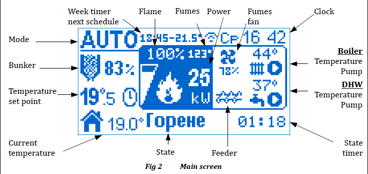
User interface
When the controller is operational, the display
looks as shown on Fig 2.
Mode:
■ ON (manual mode)
■ AUTO (automatic mode)
■ OFF
Current state:
Flame: temperature of the flue gases in degrees
Celsius or intensity of the flame in % (depending on
the configuration).
Temperature set point: desired temperature of the
heated object (room or water) or an icon for the state
of external thermostat (on or off ) if used.
Current temperature: the measured temperature of
the heated object.
Power: the current operating power when burning in
kW or relative units.
Fumes fan: revolutions of the fan in %.
Feeder: indicates that the feeder mechanism is
operational.
Clock: blinks if it is not set.
Boiler: current temperature and pump activity.
DHW: current temperature and pump activity.
State timer: elapsed / remaining time for the current
state.
Week timer: trigger time of the next week timer
event.
Bunker: pellets available in the bunker.
 Turning the device on
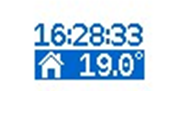
If the controller is in OFF mode and 60 seconds have passed since the last user interaction, the current time and temperature are shown on the display.
Pressing any button shows the main screen (Fig 2). Press and hold the power button in order to turn on the controller. A menu showing the modes is displayed, the active is AUTO (Fig 4). Hold the button depressed for 3 sec in order to confirm the turning on of the device. If you want to switch to ON mode, use the navigation buttons to select it, then hold the button. To turn the device off follow the same procedure. When the mode is changed the beeper signals the new mode is accepted.

Temperature set point
If the current mode is ON, use the buttons ∧ / ∨ to increase / decrease the temperature set point (the icon indicates the temperature can be changed). In AUTO mode, the temperature is fixed by the week timer or the external thermostat.
 Quick menu
To access the Quick menu, press the button < from the Main screen. For navigation use the buttons </>
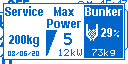
Maximum power
The controller modulates the current operating power so the temperature set point is reached. The maximum power can be limited (5 – maximum, 1 – minimum). Use the buttons ∧ / ∨ to decrease / increase the maximum power. Pressing the button ↵ sets the maximum value.
Bunker
The fuel level inside the bunker declines as the device is operating. In order to change the fuel level after loading it with pellets, use the buttons ∧ / ∨ to increase / decrease the fuel level by 5%. Press the ↵ button to increase the pellets level by 15 kg (1 bag).
Service
Indicates the remaining pellets quantity remaining to the next servicing of the device, alongside with the last date of servicing. Negative value means that the service period is overdue, indicated on the main screen by blinking icon. When you have serviced the device, press to reset the counter and the date.
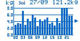 Fuel consumption
Press from Main screen to see information regarding the fuel consumption. From the sub-menu you can choose to access per day or per month statistic. A graphic shows the consumed pellets for every day / month. Use the buttons / to select a particular period and press button to switch do detailed view. In daily mode a chart per hour is shown, as in monthly mode per day. The top part of the detail view displays date / month selected, as well as the total fuel consumed for the particular period.
 Main Menu
From main screen, press button to enter the main menu. Use buttons ∧ / ∨ to navigate and button ↵ to select the current menu item. Press in order to go back one level, from the main menu you go back to the main screen. The button takes you directly to the main screen. Press ↵ to edit a parameter. In edit mode the parameter value blinks. Use </> to increase / decrease the value by 1 unit, or ∧/∨ to change by 10 units. When done editing, press ↵ to save the change or to cancel the modification and revert to the previous value.
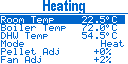 Heating
■ Boiler Temp – boiler temperature set point. The power is modulated in order to achieve the temperature set point.
■ DHW Temp – DHW temperature set point.
■ Mode – device heating mode.
▹ Heat – just the main heating is working and its temperature is monitored
▹ DHW – just the DHW heating is working and the DHW temperature is monitored
▹ Heat+DHW – both heating circuits are active
▹ DHW+Heat – both heating circuits are active, as the DHW one is with higher priority. When the DHW pump is running, the main one is stopped.
■ Pellet Adj – adjusts the fuel quantity that is being fed, depending on the fuel quality. The quantity is increased or decreased in percents of the nominal quantity.
■ Fan Adj – adjust the fumes fan relative to the service settings. The parameters shown in the menu, depend on the device configuration.
 General Settings
■ Language – user interface language
■ Brightness – set the display brightness in active mode.
■ Brightness Min – set the display brightness in idle mode. Idle mode occurs when 60 sec have passed since the last button press.
■ Contrast – display contrast.
 Week Timer
Using the week timer, the user can specify a temperature for a particular time interval of the day for a given day of the week. It consists of 6 programs, each one having 4 timers that specifies time and temperature. The time of every next timer must be after the previous one, as a value of --:-- means that the timer is not active. For example the timer configuration on Fig 11 specifies the following temperatures and periods:
■ 07:45 - 08:44 21.0°C
■ 08:45 - 17:44 18.5°C
■ 17:45 - 23:44 22.5°C
■ 23:45 - 07:44 17.5°C
Every program can be active and applied to specific days of the week. In case more than one program is active for a given day of the week, the higher priority program is the one with bigger number. Use the navigation buttons to select the current element you want to edit (program, time, temperature and day of week). Parameter editing is initiated by pressing button ↵. While editing time, using the buttons </> you decrease / increase the time by 15 min, as with ∧/∨ by 1 hour. While editing temperature, using the buttons </> you decrease / increase the temperature by 0.5 °C, as with ∧/∨ by 2 °C.
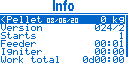
Info
On this screen usage information is displayed:■ Pellet – counter for the pellets burned from the last reset. In order to reset it, hold the button until you hear a sound signal. The counter is reset and the date is set to the current one.
■ Version – firmware version
■ Starts – controller power on count
■ Feeder – total feeder work time (HH:MM)
■ Lighter – total lighter work time (HH:MM)
■ Work total – device total work time (DddHH:MM)
■ First Start – date of first start
 Outputs
You can manually control the outputs Feeder and Fan. This is only possible if the device is in OFF mode.
Use the buttons / to choose the output you want to control and press to start / stop it. When an output is activated, a 4 min timer will stop it automatically when it expires.
■ Feeder Fill
The Feeder Fill function is used when the device is first powered on, or if the pellets have run out during normal operation.
In case the feeder is empty, turn it on until some pellets start coming down in the work area. If the feeder is not full, then during the ignition phase less pellets will be fed, which may lead to ignition failure.
■ Fan
Fan function can be used for cleaning the burning chamber from ashes.
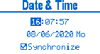 Date & Time
Set the controller's time and date. The time format is HH:MM:SS and the date format is DD:MM:YYYY. Pressing ↵ over the seconds zeroes them. All other elements can be edited the way all parameters are edited. The day of week is automatically calculated, based on the entered date. The internal clock has an internal battery, that keeps it running even when the controller is not powered. If the device is connected to the internet, the date and time can be automatically synchronized if you activate the option Synchronize.
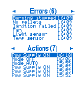 Errors / Actions
List of errors/actions that have occurred during controller operation. A maximum of 40 errors are saved and when the memory is full, the new error overwrites the oldest one. Next to the screen title in brackets Errors (6) the number of the registered errors is shown.
Press over selected element to get detailed information about it. To switch between views, use the buttons /.
■ Errors
The error list alleviates the troubleshooting of all problems that might occur during operation. The user can get help remotely, simply by reading the error to technical person and thus avoiding the need of visit.
■ Actions
User actions during the device operation are logged, for example mode change, turning device on/off, power loss and others.
 Service Menu
Warning! This menu should be used only by authorized personnel! The improper modification of parameters in this menu can hamper the correct device operation and lead to dangerous situations!
This menu is protected by 4 digit password. Use the buttons < and > to choose a digit to edit and use ∨/∧ to increase / decrease it. Press ↵ to enter the password and access the service menu.
Principle of operation
Work mode
Depending on the mode, the controller goes through series of states, so it reaches the final state for the mode. Changing the mode, makes the controller enter sequence of states, guaranteeing the correct power up or shutdown.
The boiler pump is always active, as long as the conditions for its operation are met, independent of the current mode. Exception of this rule is the case of working DHW pump and temperature of the room being reached, then the boiler pump is turned off.
ON / AUTO
Final state: Burn
When Burn state is reached, the process is controlled so that the heat needed by the system is generated.
The difference between automatic AUTO and manual ON mode is the way of determining the temperature set point. In automatic mode, the week timer or the external thermostat is used, as in manual, the user manually sets the desired temperature, ignoring the week timer or external thermostat.
OFF
Final state: Idle
When the mode is set to OFF the device will safely discontinue burning and will reach the Idle state. The system will not automatically turn itself from OFF to ON mode.
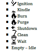
States
The state sequence is as follows:
0 Idle
1 Clean
2 Ignition
3 Kindle
4 Burn
4.1 Purge
5 Shutdown
6 Clean
7 Wait
An ongoing error monitoring (sensors or state specific) is performed during operation in all states. When an error is detected, the burning is discontinued in the appropriate sequence.
CLEAN
When cleaning, the cleaner mechanism is activated for a fixed time. The cleaning is performed when the device is powered on and off.
Ignition
A preset quantity of fuel is loaded and the lighter is activated. The device waits until the fuel is ignited by monitoring the temperature of flue gases or the flame intensity (depending on configuration). On successful ignition, it passes to the next state. If the ignition time runs out before ignition is detected, then another attempt is made, restarting the ignition process and loading 50% less fuel. When the maximum number of attempts is reached, the controller shuts down, and registers an error.
Kindle
Waiting for the burning process to stabilize. The flue temperature should raise over a set threshold or the intensity of the flame should be stable for a time above a set threshold. Meanwhile fuel is being periodically fed (if configured). If the ignition time
expires and no stable burning is detected, then a next ignition attempt will be committed.
Burn
After a stable burning is detected, the controller goes to burning state. The power (combination of supplied air and fuel) is determined by the control algorithm according to temperature(s) set pointand / or external thermostat. By varying the power, the generated heat is adjusted, satisfying the current needs of heating in the system. The burning is interrupted in the following cases:
■ User: pressing power button .
■ Clean time out: if a periodic clean is configured, then a shutdown is performed followed by clean and ignition, completing the restart cycle.
■ Week timer: if there is a time set for turning off.
■ No need of heating: when the power has been at minimum for a set time or the regulated temperature is exceeded, then the controller shuts down and transitions to WAIT mode.
■ Loss of flame: flue gases temperature or flame intensity go below threshold. An error is registered.
Purge
During the burn state, periodically a purge is committed for a fixed time. The feeder is stopped and the fan power is increased, thus cleaning the burn chamber. After the purge time expires, the controller goes back to Burn.
Shutdown
The fuel is stopped and the fan power is set according to its shutdown setting. The controller waits for all the remaining fuel to burn out by monitoring the flame detector to go below the set threshold (flue temperature or flame intensity). After the Shutdown is complete, the controller transitions to Clean state.
Wait
As in OFF mode, the device is safely transitioned to an Idle state. However, the device will automatically transition to ON mode when the system needs togenerate heat.
The device is in standby, awaiting for some of the heated objects to need heating. When all the current temperatures are above the set ones (or external thermostat), then the system should not generate any more heat and therefore stays in WAIT mode.
When the heating system cools down and a temperature drops below the set one, the device awaits a predefined time to transition back to burning and keep the system as close as possible to
the temperature set.
Service parameters
Structure
■ Global
■ Boiler
■ DHW
■ Hardware Setup
■ Temperature Control
■ Fuel
■ Clean
■ Ignition
■ Kindle
■ Burn
■ Shutdown
■ Purge
■ Opto Calibration
■ Change Password
■ Stop Work
■ Outputs Test
Parameter menus
In the table below is a description of all service parameters. They are grouped into sub menus, noted in table column Menu.
The fumes fan power is set in percents of the maximal revolutions, as 100% = Fan Max and 0% = 0 rpm.
Fuel feeding (operation of the feeder mechanism) is set in seconds with a precision of 0.1 sec and the stop time is determined of the total period as the sum of on time + stop time = Feeder Period.
|
Menu
|
Parameter
|
Description
|
|
|
|
|
|
|
|
Basis
|
|
Auger period
|
Full time (work + break ). Auger = work.
|
|
Ventilation max
|
Maximum speed of the combustion fan. It is used to calculate the percentages set as fan power.
|
|
Max gas
|
The maximum flue gas temperature above which a fault is recorded Superheating gases (if flue gas monitoring is used).
|
|
Snail current
|
The higher threshold value of the current consumption of the auger, the fixed error is a blocked auger.
|
|
Restabilization
|
shorter time than the set time , the controller will return to the burning state when the power supply is restored. Otherwise, the Shutdown state switches to and the power management error is Power Logging is requested according to the Error parameter .
|
|
Blackout
|
If the system logs an error under the conditions described in the recovery parameter. Error logging changes the mode to OFF.
|
|
Cauldron
|
|
Temperature min pump
|
The minimum threshold temperature of the heat exchanger pump.
|
|
Hyst pump
|
Hysteresis for switching the heat exchange pump on and off. Start temperature = pump minimum temperature + pump hysteresis . Stop temperature = Pump min. temperature – pump hysteresis .
|
|
Maximum boiler
|
The maximum temperature of the heat exchanger above which the error is recorded Boiler overheating.
|
|
Pump modulation
|
Enables modulation of the heat exchanger pump.
|
|
Pump selection
|
The operating temperature range where the pump output is proportionally modulated according to the minimum pump output and the maximum pump output
|
|
Insert the min pump
|
The minimum modulation power of the pump at heat exchanger temperature <= pump min. temperature.
|
|
Insert the maximum pump
|
The maximum modulation power of the pump at heat exchanger temperature >= Min. Pump temperature + pump range.
|
|
Boiler
|
|
Temperature min pump
|
The minimum start-up temperature of the boiler pump.
|
|
Delta tempe
|
The boiler temperature must be higher than the boiler temperature by the degree set to drive the pump.
|
|
Hyst pump
|
Hysteresis for starting and stopping the boiler pump. Start temperature = Temperature min pump + Hyst pump. Stop temperature = Temperature min. pump - Hyst pump.
|
|
Astep boiler ON
|
The temperature difference to get out of waiting.
|
|
Astep boiler OFF
|
required to enter the standby state .
|
|
Low priority
|
In heating + boiler mode, the boiler pump is not activated until the main heating circuit reaches the set temperature.
|
|
Hardware settings
|
|
Boiler
|
Decision to enable or disable the boiler function
|
|
AUX output
|
Functions of AUX output:
OFF: Not usable
Alarm: Activated in case of error Charging: Output for filling up fuel
Auger : Second auger
|
|
Exit cleaning
|
Clean Output Features:
Purge: A purge mechanism that activates during the purge state Chimney: Chimney fan that is activated when the main fuel fan is active.
|
|
Ventilation car
|
Performance in percent for the Clean output when configured as a chimney fan.
|
|
Entry level
|
Function for level entry:
OFF: Not usable
Pellet: Pellet level in the hopper
Cleaning: Position of the cleaning device
|
|
E1 cleaning
|
Direct transition to the cleaning process in the event of an E1 input error.
|
|
Е1 reversal
|
Reverse the active fault condition entry E1 (normally closed sensor).
|
|
Input E2
|
Input function for E2 errors (active status input error):
• Chimney: Chimney pressure • Door: Open the appliance door. When the door is opened, it goes into a rest state, and after closing, the previous state is restored.
|
|
Е2 reversal
|
Reverse the E2 active fault condition entry (normally closed sensor)
|
|
Boiler t1
|
is read by a temperature sensor t1 instead of the normal t2 .
|
|
Uploader
|
Operating time at the filling station when the pellet level in the hopper is low.
|
|
Temperature control
|
|
Thermostat
|
Control of the thermostat:
• Room temperature: The room temperature can be read with an NTC sensor. • Heat exchanger: The temperature of the heat exchanger (water). • Ext NC: The external thermostat is normally open.
• Exception number: The external thermostat is closed in the default position.
|
|
Waiting time ON
|
The time required to switch to the standby state. If the device is in standby mode and needs to heat more than the set time, the ignition procedure starts.
|
|
A week of free time
|
The wait is the time required to change from write to state. If the device is on fire and operates at a minimum power greater than the set time, the extinguishing procedure starts.
|
|
Step temp ON
|
The difference between the current temperature and the set temperature, below which the machine immediately switches from standby to burning.
|
|
Step temp OFF
|
the current temperature and the set temperature at which the device immediately switches from burning to standby.
|
|
Astep boiler
|
prompts the standby state .
|
|
Performance level
|
Performance number. The minimum power is 2. Increasing this parameter makes the power modulation smoother and faster.
|
|
Fuzzy period
|
The duration of the power change calculation. The more inert the controlled object, the longer the period should be, and vice versa. If the operating performance fluctuates between extremes when the set temperature is reached, increase the duration. With the high inertia of the set temperature, reduce the duration.
|
|
Burnt temperature
|
The output is modulated depending on the set temperature so that the temperature of the flue gas does not exceed the parameter.
|
|
Pellets
|
|
Stream snail
|
Fuel dispenser capacity - the amount of pellets delivered per minute.
|
|
Tank volume
|
Tank volume to calculate fuel level.
|
|
Service
|
The amount of pellets burned, after which your device must be cleaned.
|
|
Energy
|
Pellets are energy products in Wh /kg
|
|
Show KW
|
Allows the user to choose to display current in units of measurement (kW).
|
|
Ignition
|
|
Period
|
The ignition test time includes the time required for ignition and ignition conditions. After the time has elapsed, the next ignition test must be performed.
|
|
Attempt
|
The number of attempts and then an ignition error are displayed.
|
|
Facara detection
|
Method of recording the combustion:
Light: Optosensor to monitor the intensity of the flame light
Gases: The ignition is detected by the temperature of the flue gas
|
|
Fan
|
Fan performance in the ignition state.
|
|
Loading pellets
|
Pellet feeding time for the first dose
|
|
Delta flue gas
|
The rise temperature of the flue gases in relation to the ignition start time , above which ignition can be considered to have occurred.
|
|
Light level
|
Light sensor level above which ignition is considered.
|
|
Snail 2
|
Working time in percentage for worm2 compared to the main worm. With a setting of 200%, auger2 runs twice as long as the main auger.
|
|
Stabilization
|
|
Fan
|
Fan performance in the stabilization phase.
|
|
Snare drum
|
The operation of the worm during stabilization.
|
|
Flue gases
|
Flue gas temperature, for transfer to combustion.
|
|
Duration of light
|
The time during which the level of the light sensor is continuously above the ignition → light level, after which the ignition state ends.
|
|
Ignition
|
The time until the igniter remains on during the stabilization phase. The minimum value of the parameter is OFF.
|
|
Burn
|
|
Min. vent
|
Fan speed at minimum power.
|
|
Min feeder
|
Operation of the auger at minimum power.
|
|
Max vent .
|
When operating at maximum fan speed. Auger operation at maximum power.
|
|
Max feeder
|
Auger operation at maximum power.
|
|
Feeder
|
working time in percentage for the main screw . With a setting of 200%, auger 2 works twice as long as the main auger.
|
|
Clean
|
|
Period
|
Operating time in the burning state, after which the device is switched off, cleaned and re-ignited. Minimum value of the OFF parameter.
|
|
Fan
|
Fan performance in cleaning state.
|
|
Time ON
|
The duration of the state is cleaning when the machine is started.
|
|
Time OFF
|
Cleaning status duration when machine is turned off.
|
|
Output
|
period of the cleaning structure . Minimum value of the OFF parameter.
|
|
Cleaning
|
|
Period
|
Clean reset period. When the device is in the burned state and the set time expires, a reset procedure is performed (shutdown, cleaning and re-ignition ). The minimum value of the parameter is OFF.
|
|
Time
|
The duration of the cleaning state.
|
|
Fan
|
Fan power in flushing state.
|
|
Clean
|
Activate the Clean output without changing the fan power.
|
|
Shutdown
|
|
Fan
|
Fan power when off.
|
|
Light level
|
Light sensor level below which the Light Time countdown begins.
|
|
Light time
|
Time during which the light sensor level is continuously below Shutdown. Light level. When the time expires, the shutdown state ends.
|
Additional menus
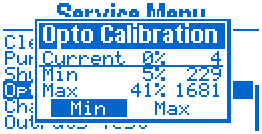 Opto Calibration
Here you can set the minimum and maximum value for the light sensor level. They define the limits, that are used to calculate the flame intensity in percents (0% = Min, 100% = Max.)
The table shown on display, constitutes of the following columns:
■ Reading:
▹ Current: reading of the light sensor in the current moment
▹ Min: value set for minimum intensity (0%)
▹ Max: value set for maximum intensity (100%)
■ Percent from the whole measured range
■ Value in absolute units (from 0 to 4095), corresponding to the light sensor input voltage (I1).
Use the navigation buttons to choose a parameter to edit or action:
■ Absolute value Min/Max – edit the absolute value, used to set the min/max limits.
■ Current value Min/Max – choosing some of the buttons, the according parameter takes the current value of the light sensor and is saved.
 Change Password
You can change the password for accessing the service menu from here. Enter a new password two times, as the second time the password should match the first one. Only then it will be accepted and saved.
After changing the service password, you will be asked again for it in order to access the service menu.
 Stop Work
The device can be forced to stop, ignoring the conditions for needed to complete a shutdown procedure. If the device is working, first a transition to Clean state is made, as a repetition of Stop Work command switches the device to OFF mode.
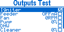 Outputs Test
Warning! Improper activation of the controller's outputs can lead to dangerous situation!
Every single one of the controller's outputs can be manually activated. This screen is only accessible if the controller is in OFF mode and in Idle state.
Use the buttons ∨ and ∧ to choose an output to activate. Press ↵ to toggle on and off the current output. The check box on the right side of the screen indicates its current condition.
There is additional information, located next to the check box, for the following outputs:
■ Feeder: Feeder current consumed, measured by a current sensing detector in the controller. This value can be used to establish the normal work current as well as the block current of the feeder.
■ Fan: Revolutions per minute measured by the hall sensor (I2). Tests the correct operation of the sensor and determines the maximum speed of the fan installed.
■ Pump: Pump power in percent. Use the buttons </> to decrease/ increase the power, when the output is on.
Errors
When an error is registered, the controller goes to shutdown state if it is in Burn state.
The only exception is error Overheat Bunker. When it occurs, the controller goes straight to Clean state even if the work mode is OFF.
The possible errors are:
■ Temp sensor: Temperature sensor (from t1 to t4) is either broken or shorted (according to the error description).
■ Ignition failed: The device failed to ignite.
■ No pellets: The pellet level sensor has determined that there is no more fuel and refill time has expired.
■ Cleaner: The cleaner mechanism is not in the right position according to the level input sensor (I3).
■ Burning stopped: In Burn state, a loss of flame is detected according to the flue gases temperature or light intensity.
■ Power failure: The power was cut for time exceeding the recovery time.
■ Feeder blocked: The current, consumed by the feeder is above the threshold.
■ Fume pressure: error input E2 activated.
■ Clock: Error occurred in the real time clock module. Does not force the device shutdown.
■ Overheat: Overheating is registered in some of the following modules (according to error description):
▹ Water: boiler temperature exceeded the
maximum.
▹ Flue: flue gases temperature exceeded
maximum.
▹ Bunker: error input E1 activated.
Actions
The possible errors are:
■ Pow Supply ON: Device connected to power.
■ Pow Supply OFF: Device disconnected from power.
■ Mode ON: Device switched to ON mode.
■ Mode AUTO: Device switched to AUTO mode.
■ Mode OFF: Device switched to OFF mode.
■ Service Menu: Service menu accessed.
■ Service: Device serviced.
Connections
It is mandatory to use mains switch and fuses for connecting the device to mains power (L and N) and the total power consumption of all modules should be taken into account! The whole product including all of inside electric units should be earthed (connected to PE)!
|
Inputs
|
|
Pt1000
|
T1
|
Flue gas temperature sensor
|
|
NTC 10K
|
T2
|
Heat exchanger with temperature sensor
|
|
NTC 10K / Bé – Off
|
T3
|
Room temperature sensor / room thermostat
|
|
NTC 10K
|
T4
|
DHW boiler temperature sensor
|
|
Light sensor
|
i1
|
Flame intensity sensor
|
|
GND device level
|
i2
|
Daytime sensor to read combustion fan speed
|
|
i3
|
Position of capacitive / inductive pellet level sensor / cleaning mechanism
|
|
Opto -isolated input 230V AC
|
e1
|
Reverse combustion error (bunker overheating)
|
|
e2
|
Chimney pressure error/door
|
|
230V 50Hz
|
network
|
Power supply, internal safety 6.3A
|
|
Outputs
|
|
Relay
|
O3
|
Ignition
|
|
Triac
|
O1
|
Main auger (fuel mechanism)
|
|
O2
|
Internal worm
|
|
O4
|
Fan for combustion
|
|
O5
|
Heat exchanger pump (water/fan pump)
|
|
O6
|
DHW pump
|
|
O7
|
Cleaning/chimney fan
|
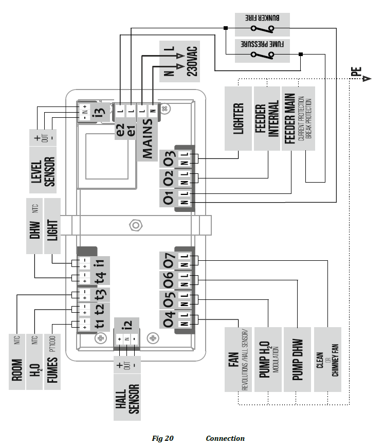
Mounting
The controller should be mounted on a flat surface with square opening sized 128 x 57 mm.
To mount the controller, first unscrew the mounting bracket, then put the controller in the opening. Fix it in place by putting the bracket on the back side and fasten the screw (Fig 22).
Technical data
Voltage: 230 V, 50 Hz
Controller power consumption: 3.6 VA
Outputs total current: 6.3 А
Operating temperature: 0 ... 40 °C
Protection rating: IP 20
Dimensions: 138 x 67 x 52 mm
Display: LCD 128 x 64 px
Temperature sensor: Pt1000 -40 ... 250 °C
Temperature sensor: NTC -40 ... 125 °C
