Celsius Classic P-V 25 solid boiler
These boilers are easy and economical to operate. Their firebox is made of 5 mm thick steel by welding folded edges. The 3 boiler doors are made of cast iron to satisfy all necessary operational functions (filling, cleaning, air control). These boilers have one firebox behind the middle door.
Advantages of Celsius V and P-V classic solid boilers:
- The classic boilers provide even heat distribution in a Celsius Heating System, whether used on its own or with open fireplaces or stoves.
- Uses renewable energy.
- Classic boilers produce useable energy from dry non-woody biomass.
- If required, coal can be used as a source of fuel.
- Firebox and internal frame are 5 mm thick resistant steel for durability and high pressure tolerance.
- Operation is easy and economical.
- Able to heat with other boiler or heat source (maximum of 2 bar pressure) in the one heating system.
- Suitable for radiator, underfloor or combined heating system.
- Able to produce drinkable hot water with domestic hot water package.
- These boilers are easy and economical to operate. Their firebox is made of 5 mm thick steel by welding folded edges. The 3 boiler doors are made of cast iron and satisfy all necessary operational functions (filling, cleaning, air control). These boilers have one firebox behind the middle door.
RECOMMENDED FUELS:
• Non-woody biomass
ACCESSORIES:
• Boiler thermometer
• Filling/draining tap
• Fire grates (grills)
OPTIONAL ACCESSORIES:
- Automatic draught regulator
- Security valve (2 bar)
- Pump heating system in case of pump system controller
- Heating system controllers
- Celsius anticondensing unit package up to 65 kW
- Celsius safety heat exchanger (to avoid overheating)
- Stainless steel chimney system
- Slag scraper, ashpan
| TECHNICAL SPECIFICATIONS |
| Modul |
P-V 25 |
| Firing door size (mm) |
200*300 |
| Maximum heat output (kW) |
24 |
| Heating-system dependant heatable air-space(m3) |
250-450 |
| Fuel-dependant efficiency (%) |
78-82 |
| Heating water connection (") |
2" |
| Uptake connection (mm) |
132 |
| Height (mm) |
1150 |
| Width (mm) |
450 |
| Depth (mm) |
500 |
| Weight (kg) |
180 |
| Water volume (l) |
52 |
| Max. operating pressure (bar) |
2 |
| Max. operating temperature (°C) |
90 |
| Test pressure (bar) |
4 |
| Firebox size (mm) (height*width*depth) |
500*320*370
|
|
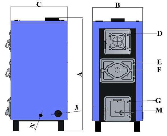
Mark
|
Description
|
|
A
|
Height of boiler
|
|
B
|
Width of boiler
|
|
C
|
Depth of boiler
|
|
D
|
Cleaning door
|
|
E
|
Firing door
|
|
F
|
Secondary draught regulator slot
|
|
G
|
Ash removal door (primary draught regulator)
|
|
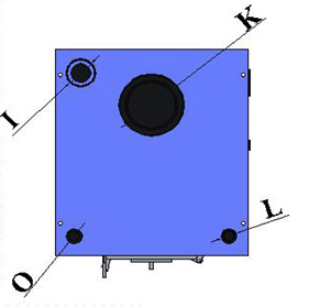
I
|
Forward water connection
|
|
J
|
Return water connection
|
|
K
|
Uptake connection
|
|
L
|
Automatic draught regulator connection
|
|
M
|
Manual and automatic draught regulator option
|
|
N
|
Filling/draining tap connection
|
|
O
|
Boiler thermometer connection
|
F-Celsius anticondensing package to 65 kW
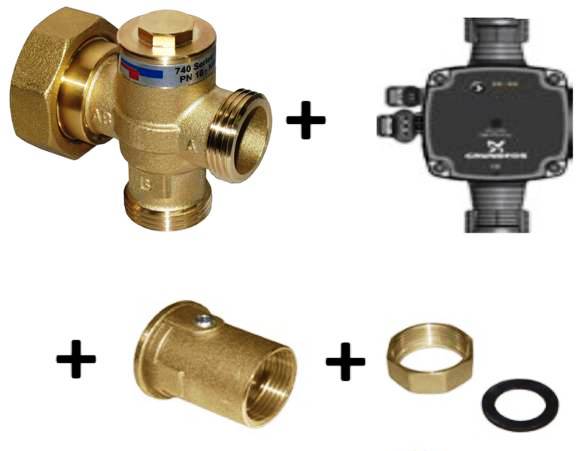
Boiler protection unit to prevent condensation
Condensation is an often experienced phenomenon during the use of the solid fuel boilers which is always harmful, will cause lifespan shorthening, efficiency drop, and higher heating costs.
Content of equipment:
- circulation pump (Grundfos UPM3 25-70 Hybrid)
- pump hollander (ball tap) 1 piece
- Celsius boiler protection valve
- to 65kW KVS 7,2
Principle of operation:
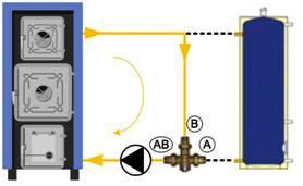
1. Starting the system (heating the boiler)
After the launching of the boiler, the thermic valve is fully closed towards the user (gate A) and remains in this condition until the fluid is warmed up by the heating source, gets the opening temperature of the thermic valve (corresponding to the calibration value, f.i. 55°C). During this step the fluid sent by the boiler fully recycles through the by-pass (gate B) so the boiler temperature rises very quickly.
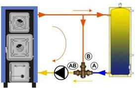
2. Loading the system (heating the tank)
Reaching the opening temperature (f.i. 55C), gate A proportionally starts to open while gate B proportionally starts to close. The boiler temperature slowly rises, giving energy to the end user, but the returning temperature will not decrease below the calibrated temperature (f.i. 55°C).

3. System operation
Starting from point 2, the flow temperature progressively increases to fully open gate valve A. This will correspondingly close gate valve B. This happens at approximately circa 10k higher than the calibration or opening temperature (therefore in this example at 65c). Now the installation is fully operational the supply fluid temperature can increase to set value.
For example, if the valve opening temperature is 55°C, then it is totally opened in the direction of A → AB in case of +10°C.
Celsius safety heat exchanger
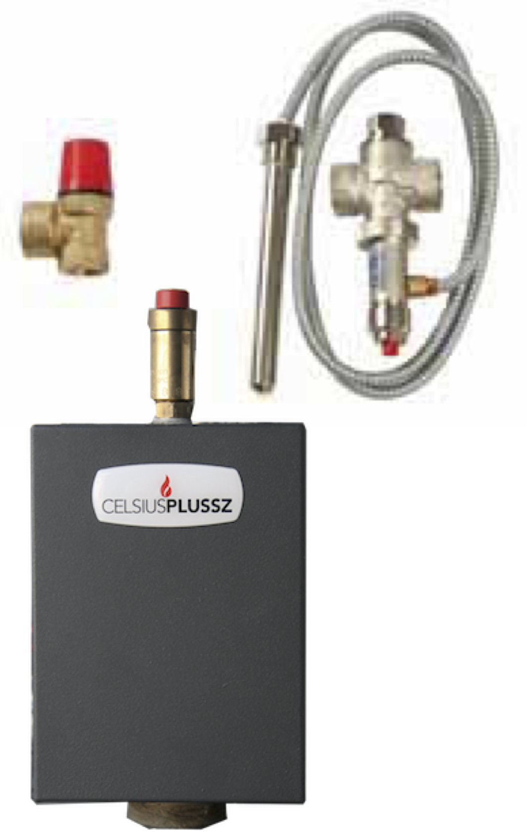
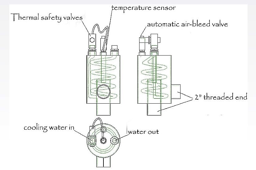
It protects the boiler and environment if the boiler is overloaded and the heating system can not heat distribute (There is not buffer tank and irregular usage).
Content of equipment:
- Celsius safety heat exchanger
- Vent valve
- Thermostatic security valve (opening temperature 98°C)
- Pressure security valve (2bar)
Applicable to the following boiler types:
Celsius classic, Celsius C and Celsius Combi boiler
Euroster 11E pump controller
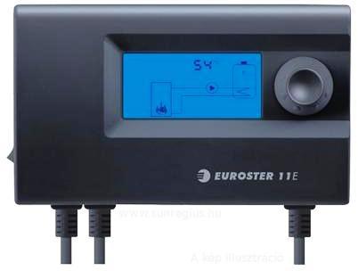
Central heating/Utility hot water system pump controller
Euroster 11E is a modern microprocessor-based controller used to control central heating (CH) system pump or utility hot water (UHW) system pump.
The Euroster 11E controller features the ANTY STOP function that prevents idle pump rotors against seizing. Once the heating season is over, every 14 days the function automatically turns ON the pumps for 30 seconds. To that end the controller must be left powered up.
The Euroster 11E controller may be operated in two modes: it may control CH system pump or UHW system pump. In the former mode the CH system pump is engaged if sensor temperature has exceeded the preset limit. In the latter mode the UHW system pump is kept running until sensor temperature reaches the preset value.
- Set 1 has been complied for layouts in which CH system pump is control,
- Set 2 has been complied for layouts in which UHW pump is controlled.
Connection diagrams
Central heating pump control mode:
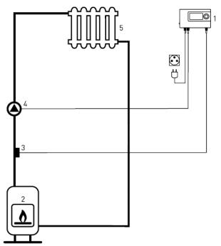
1. Euroster 11E controller
2. CH boiler
3. Heat source temperature sensor
4. CH pump
5. Radiator (heat load)
Domestic hot water pump control mode:
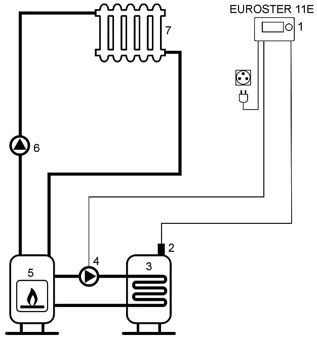
- Euroster 11E controller
- DHW tank temperature sensor
- DHW tank
- DHW pump
- CH (wood pellet) boiler
- CH pump
- Radiator (heat load)
Elements of the controller:
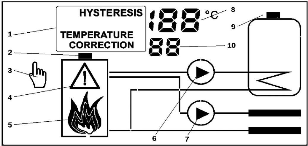
- Name of the controlled parameter
- Heat source (boiler)
- Manual operation mode (icon lit while the temperature is manually controlled)
- Alarm – (icon blinks in case of an alarm)
- State of the heat source
- DHW system pump icon lit while the pump is running
- CH system pump icon lit while the pump is running (CH system control mode)
- Heat source and other parameter value
- DHW tank temperature sensor icon
- Menu option number
Technical features:
|
Min. temperature |
Max. temperature |
| Controlled temperature |
20 |
80 |
| Hysteresis |
2 |
10 |
| Temperature sensor correction |
-5 |
5 |
| Manual operation |
0 (ki) |
1 (be) |
| Operating voltage |
230V, 50Hz |
| Ratted wattage |
1,6W |
| Output load of circuit pump |
200W |
| Potential independent output |
100W |
| Environmental temperature |
0 - 65°C |
| Temperature measurement range |
0 - 110°C |
| Operation temperature range |
20 - 80°C |
| Hysteresis |
2 - 10°C |
| Temperature accuracy |
1°C |
| Protection |
IP40 |
| Display |
LCD
|
